Restoring a Classic Spectrum Analyzer Part 4 - Mainframe Restoration
10/04/13 20:10
In Part 3, I described how the MMS modules installed into the spectrum analyzer were individually stripped down, thoroughly cleaned and inspected and carefully re-assembled. The next phase of the refurbishment was to strip down and clean both the 70004A Colour Display mainframe and the 70001A expansion mainframe.
First was the 70004A mainframe. Initial inspection didn’t reveal anything unusual. It was dusty and grimy in the usual places such as fan grills, vent grilles, knobs, and buttons. Unfortunately, the aluminum HP nameplate was somewhat bent and distorted. Sticker residue from previous label removals was present in various locations. Sometimes, removing this residue is the most time consuming task.
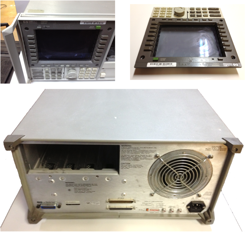
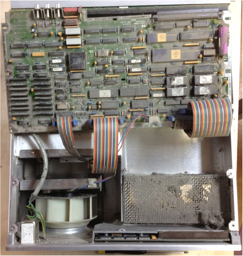
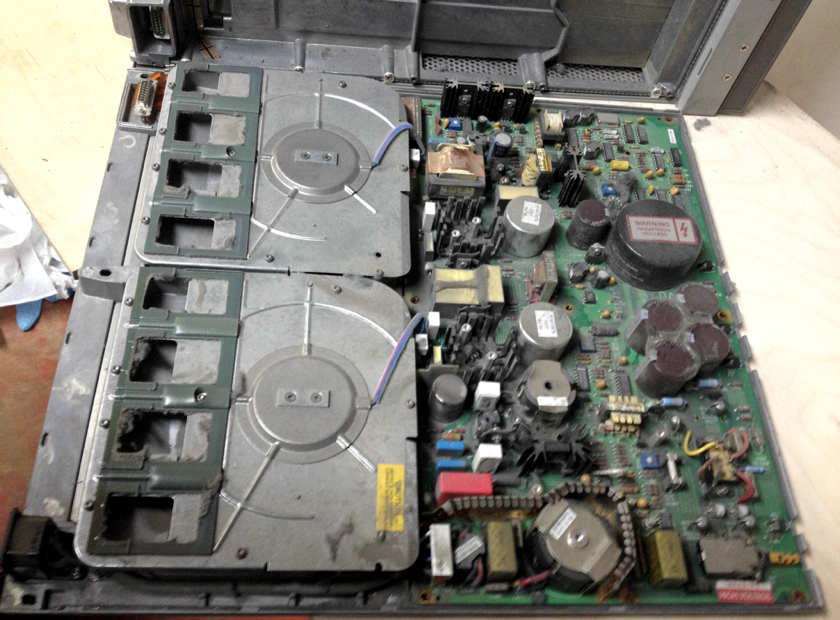
However, opening the cover revealed the true extent of the job ahead! Large amounts of dust and grime covered the entire mainframe, especially around vent grilles and the control PCB.
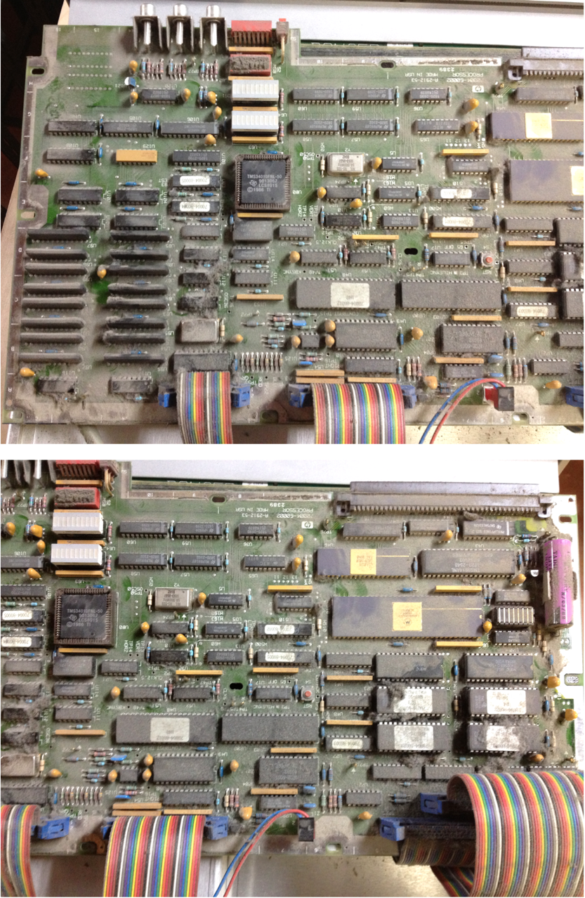
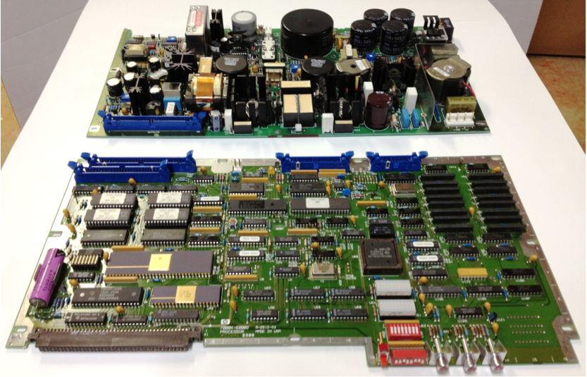
I disconnected all of the sub-assemblies and carefully removed them. I started by cleaning the two main PCBs: the A4 Power Supply PCB and the A5 Processor PCB. I used a shop vac to remove the bulk of the dust and debris, followed by compressed air to remove the last of the dust. I carefully cleaned the PCB with some alcohol and Kim-wipes to remove staining and grime. After some time, it starts to look pretty good! Here is the A5 Processor PCB after cleaning:
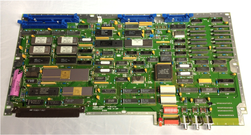
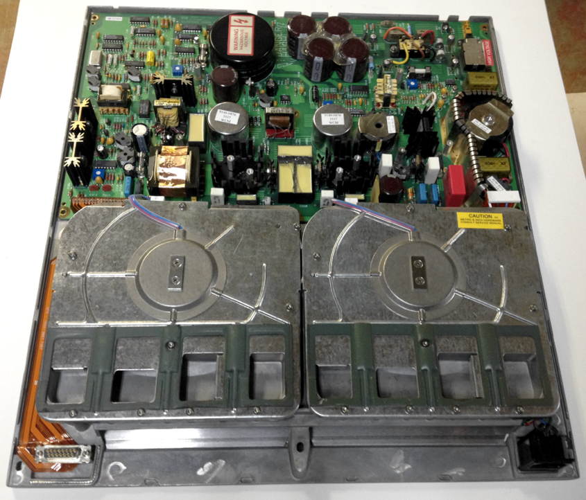
Here are both the A4 Power Supply and A5 Processor PCBs:
I then followed this task by cleaning the ribbon cable assemblies and other wiring harnesses.
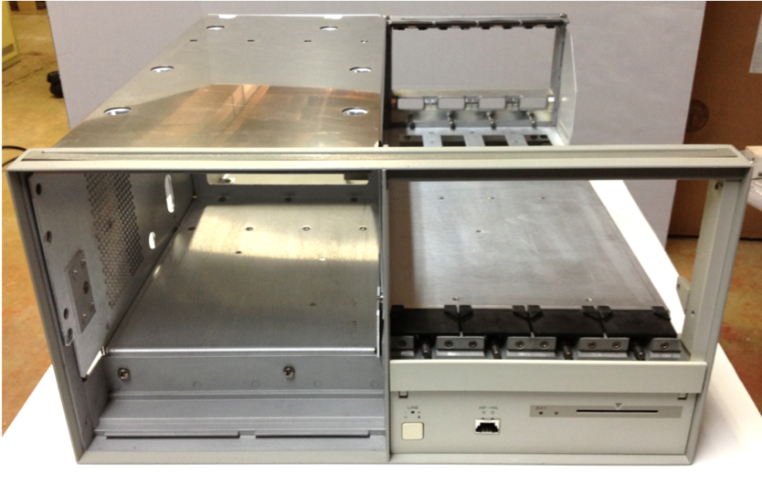
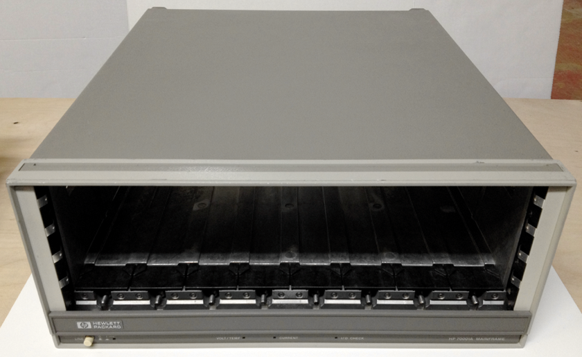
The 70004A mainframe was completely stripped down to a bare chassis. After a great deal of cleaning, it started to look quite good. At this point, I was ready to start re-installing and reconnecting sub-assemblies.
Here is the front of the 70004A after cleaning:
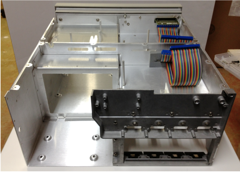
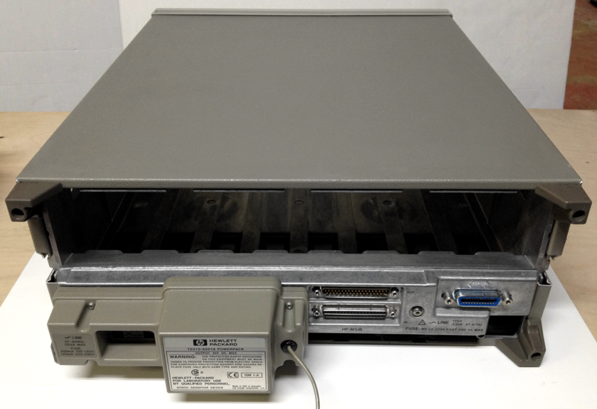
and here is a view from the rear:
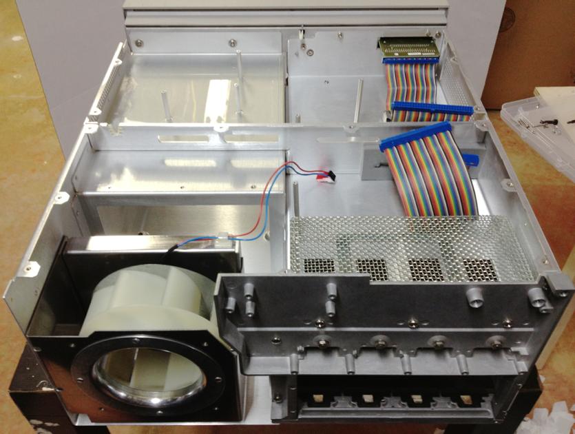
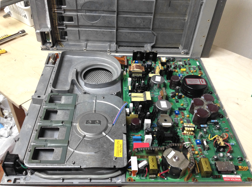
The fan assembly was particularly dirty and required a great deal of attention. However, it did turn out really well:
I slowly and carefully reassembled the 70004A. Just before installing the Sony colour monitor into the chassis, I temporarily connected it as best as possible just outside of the mainframe so that I could readjust the display quality, in particular to correct the purple bias. After a little adjustment, I corrected the colour bias and fine tuned the overall display quality.
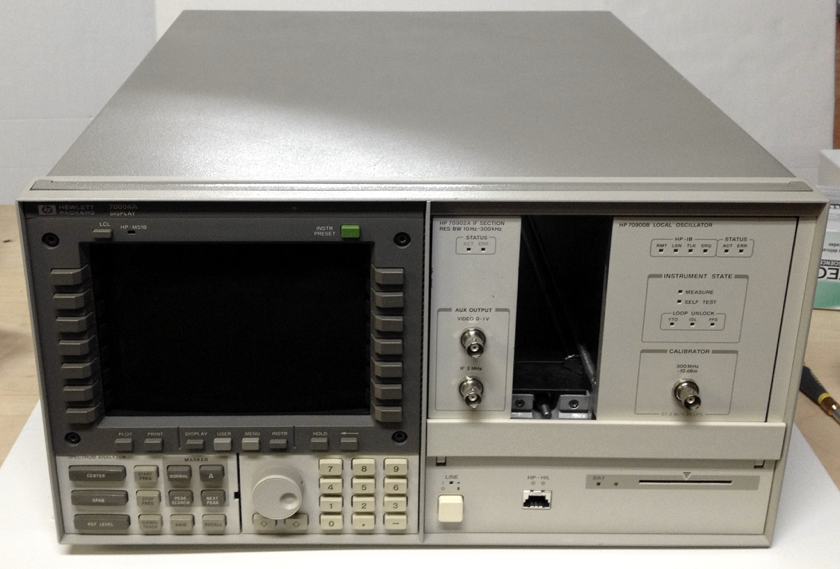
Here is the 70004A after complete re-assembly. It is amazing how nice it starts to look after removing grime from the buttons. I also managed to fixed the dented aluminum HP name plate.
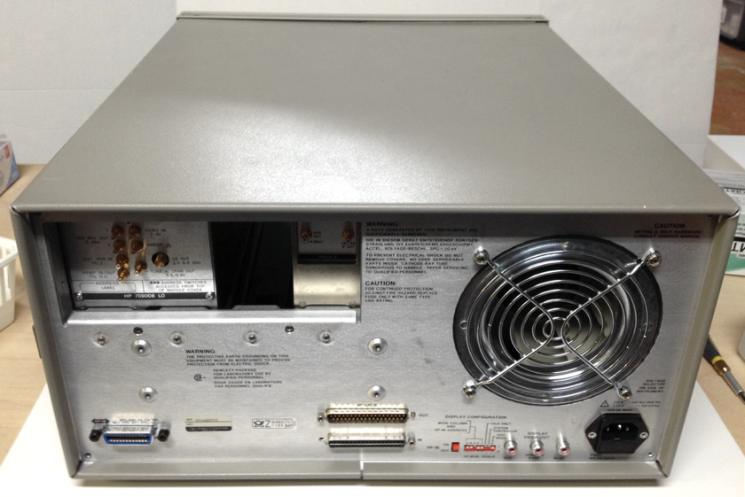
This is the completed 70004A as viewed from the rear:
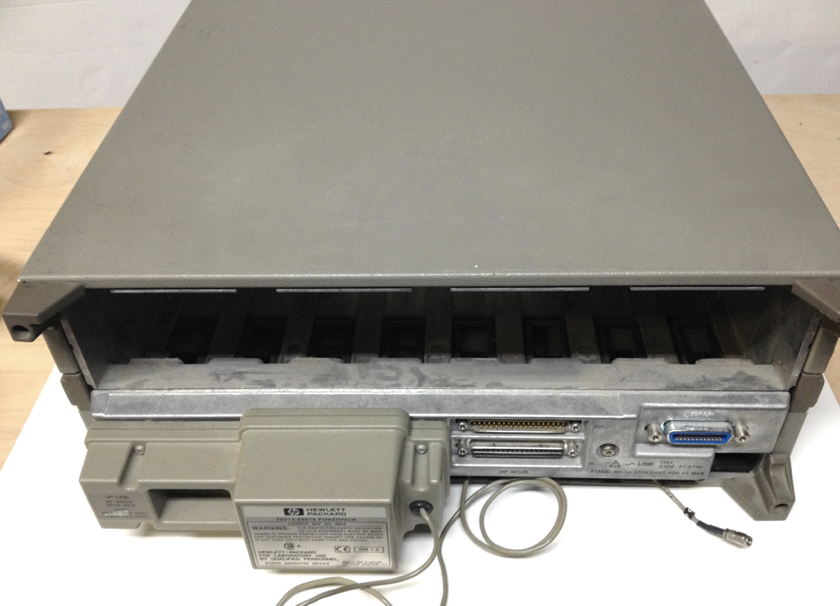
The next task was cleaning the 70001A secondary mainframe. As expected, it had significant accumulations of dust, dirt and grime. Also, the latching bottom front panel was plastered with stickers and labels which were extremely difficult to remove. Here is the 70001A prior to disassembly and cleaning:
After opening the unit, I discovered more tedious PCB cleaning tasks:
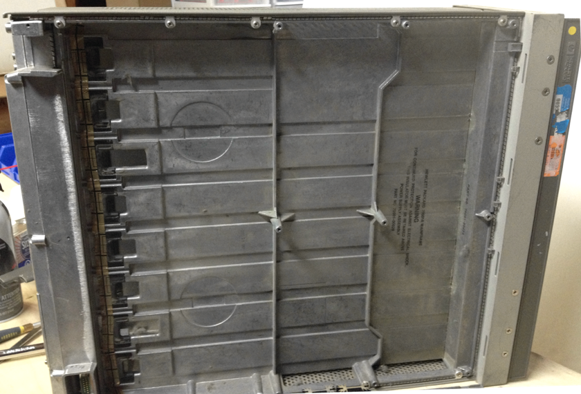
Again, after a great deal of careful disassembly and cleaning, the unit started to look quite good:
Finally, after careful re-assembly, the 70001A mainframe was completed and looked much better:
In the final article in this series, I will show the final configuration of the instrument with all of the MMS modules installed into their desired slot. Also, the empty slot filler panels will be installed, as well as the rack mount ears and installation into the portable 19” rack.
First was the 70004A mainframe. Initial inspection didn’t reveal anything unusual. It was dusty and grimy in the usual places such as fan grills, vent grilles, knobs, and buttons. Unfortunately, the aluminum HP nameplate was somewhat bent and distorted. Sticker residue from previous label removals was present in various locations. Sometimes, removing this residue is the most time consuming task.
However, opening the cover revealed the true extent of the job ahead! Large amounts of dust and grime covered the entire mainframe, especially around vent grilles and the control PCB.
I disconnected all of the sub-assemblies and carefully removed them. I started by cleaning the two main PCBs: the A4 Power Supply PCB and the A5 Processor PCB. I used a shop vac to remove the bulk of the dust and debris, followed by compressed air to remove the last of the dust. I carefully cleaned the PCB with some alcohol and Kim-wipes to remove staining and grime. After some time, it starts to look pretty good! Here is the A5 Processor PCB after cleaning:
Here are both the A4 Power Supply and A5 Processor PCBs:
I then followed this task by cleaning the ribbon cable assemblies and other wiring harnesses.
The 70004A mainframe was completely stripped down to a bare chassis. After a great deal of cleaning, it started to look quite good. At this point, I was ready to start re-installing and reconnecting sub-assemblies.
Here is the front of the 70004A after cleaning:
and here is a view from the rear:
The fan assembly was particularly dirty and required a great deal of attention. However, it did turn out really well:
I slowly and carefully reassembled the 70004A. Just before installing the Sony colour monitor into the chassis, I temporarily connected it as best as possible just outside of the mainframe so that I could readjust the display quality, in particular to correct the purple bias. After a little adjustment, I corrected the colour bias and fine tuned the overall display quality.
Here is the 70004A after complete re-assembly. It is amazing how nice it starts to look after removing grime from the buttons. I also managed to fixed the dented aluminum HP name plate.
This is the completed 70004A as viewed from the rear:
The next task was cleaning the 70001A secondary mainframe. As expected, it had significant accumulations of dust, dirt and grime. Also, the latching bottom front panel was plastered with stickers and labels which were extremely difficult to remove. Here is the 70001A prior to disassembly and cleaning:
After opening the unit, I discovered more tedious PCB cleaning tasks:
Again, after a great deal of careful disassembly and cleaning, the unit started to look quite good:
Finally, after careful re-assembly, the 70001A mainframe was completed and looked much better:
In the final article in this series, I will show the final configuration of the instrument with all of the MMS modules installed into their desired slot. Also, the empty slot filler panels will be installed, as well as the rack mount ears and installation into the portable 19” rack.